SR25 Front Outboard Assembly
I designed two 7075-T6 parts - a brake caliper and a front hub - for an off road competition vehicle competing in the Baja SAE racing series as part of a major front outboard assembly redesign. In doing so, I reduced suspension loading through our vehicle by over 33%.
I designed the components in NX, validated them through physical testing, FEA in Ansys, and hand calculations. My parts were stronger, easier to machine, and easier to assemble than the previous design.
As a result, my components saw zero failures, and aided our team in achieving a 4th and 6th place overall finish at Baja SAE Arizona and Baja SAE Maryland.


Brake Caliper
I designed a floating caliper with custom pads for the 2025 competition vehicle that took up less space than the previous years’ design. This, alongside an increased rotor diameter, allowed me to move the entire brake assembly closer to the upright and away from the hub. With the brake system out of the way, our outboard assembly could accommodate a reduced spindle length, which reduced our vehicle’s suspension joint loads by 500+ lbs.
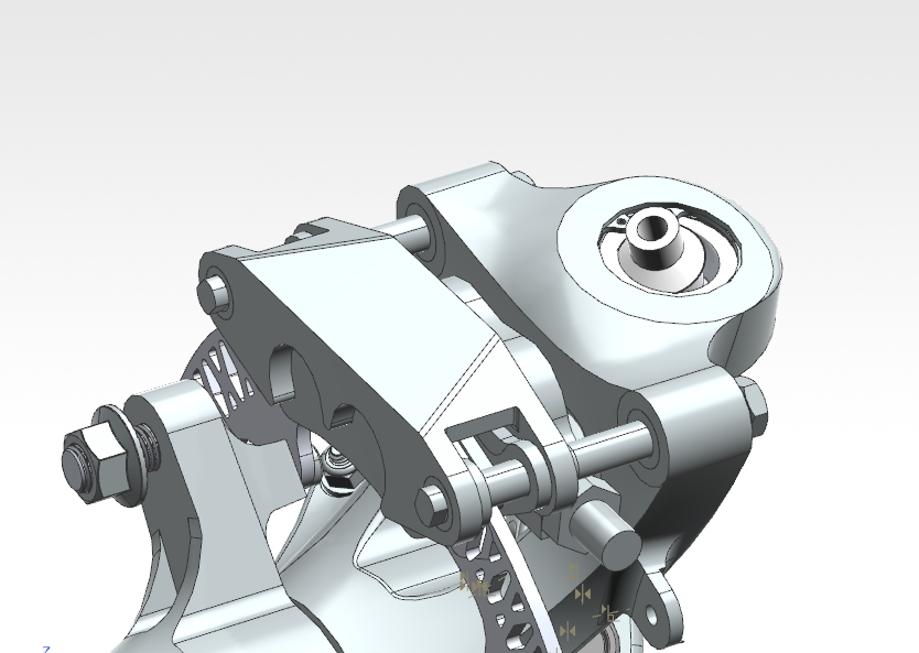


My design was light, strong, and small enough to fit between the steering knuckle and the rim. I also integrated it in a way that made the steering knuckle lighter - by mounting it closer to the top, where there was already material to accommodate a spherical joint. I did this with a modified shoulder bolt and a special upright spacer. These images also show how the increased rotor diameter allows the brake caliper to be moved into the page (from this perspective).


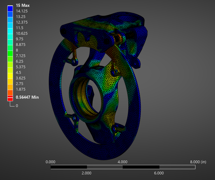
I did the FEA in Ansys. I calculated both the pressure the pistons saw from the master cylinder and the maximum braking torque and used them as my loads. I also included the upright and its accompanying loads I achieved from our wheel force transducer testing to make sure the caliper could handle suspension loads, too.
Front Hub
For the SR25 competition vehicle’s front hub, I also had to make changes to accommodate the required suspension load decrease. The main one was that the arms of the hub which the tire got mounted on was moving closer to the car, which required me to spec a new bearing stack.
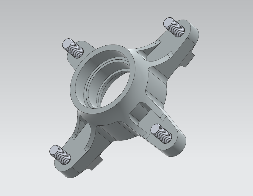

The new bearings I’d selected - by making a model in KISSSoft by taking loads I had from our wheel force transducer testing to rapidly iterate between stacks - had a large bore diameter, which also allowed me to bore the spindle out, saving weight.
Another aspect of this hub was that it had to transmit torque for our 4WD system, and to do so, we used a sprag clutch (a type of one-way bearing). Traditionally, the team used a press fit outer race and a keyed inner race, but the keyed inner race took up too much space and didn’t allow me to bore the spindle out as much as I wanted. So, I found a sprag clutch from GMN Bearing that had a press fit outer race and a press fit inner race.
We had to test to make sure the inner race was capable of transmitting the torque we wanted - the outer race had already been vetted from years of experience, but I’d never press fit a bearing race on a titanium shaft before.


To test the inner race’s torque transferring capability, I first specified what the press fit should be using KISSSoft. GMN Bearing had given us a recommendation, but they had never pressed their clutches onto titanium before. Then, we machined a shaft and a random steel bearing inner race and pressed them together. Then I used a jig we already had for torque testing on one of the hubs and spun it with a torque wrench.
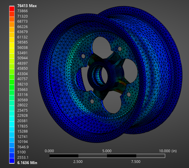
I also conducted intensive FEA on the design as a whole. I ran 12 load cases from the maximums and minimums in all directions to verify the assembly met our derived requirements. I also included the rim and outer races of the bearing stack, as I knew they added considerable rigidity.